Foundation fieldbus
It based on IEC 61158 standard (1999). Basically Foundation fieldbus did the same job as like other fieldbus only the difference is that, its architecture.
So let's see the architecture of foundation fieldbus...
It supports the OSI architecture as shown below,
Foundation fieldbus technology consist of three parts
1. Physical layer
2. Communication stack
3. User application
The first component in any foundation fieldbus segment is H1 interface module, here we have connected a H1 connection to Delta V DCS as shown in figure below,
This connection could be with any DCS like yokogawa, Honeywell, ABB etc. It is independent of manufacture. But the host is where your all controlling will be done and this is what a LAS means link active scheduler. It means it schedules the work for every activity on fieldbus network.
The second component is power supply following picture will shows the example of pepperl Fuchs foundation fieldbus power hub.
There are different number of segment option, this is a four segment redundant power supply. Power supply main role is to provided matching impedance to fieldbus segment. It is also consist of built in diagnostic module allows you to monitor the physical layer for all work foundation fieldbus segment and these signal transmitted through diagnostic bus from the backplane of fieldbus motherboard.
For more information click here
For wiring demonstration click below...
It based on IEC 61158 standard (1999). Basically Foundation fieldbus did the same job as like other fieldbus only the difference is that, its architecture.
So let's see the architecture of foundation fieldbus...
It supports the OSI architecture as shown below,
 |
| OSI Architecture |
Foundation fieldbus technology consist of three parts
1. Physical layer
2. Communication stack
3. User application
- Physical layer - It is the standard defined by international electromechanical commission (IEC). It is actually deal with how communication work physically. This layer receives messages from communication stack and converts the message into physical signals on the fieldbus transmission medium and vice versa.
For encoding messages on Foundation fieldbuses, Manchester encoding used as shown below
 |
| Manchester Encoding |
Advantage of Manchester biphase-L Encoding
Manchester encoding is synchronous clock encoding technique used by
the physical layer to encode the clock and data of
a synchronous bit stream.
In this technique, the actual binary
data to be transmitted over the cable is encrypted.
- Data Link Layer- Data link layer provides or increase the reliability of electrical layer. Data link layer (DLL) controls transmission of messages into the fieldbus. The DLL manages access to the fieldbus through a deterministic centralized bus scheduler called the link active scheduler (LAS).
- Network Layer- It is concerned with logical addressing process of nodes and take care of networking problems (Where the information should go).
- Transport Layer- It is responsible for the end to end communication control.
- Session Layer- It is concerned with any execution of remote actions and it fix the session for certain applications like email service.
- Presentation Layer- It is responsible for the data interpretation, which allows for interoperability among different equipment's.
- Application Layer- It is subdivided into
1. Fieldbus access sub layer
2. Fieldbus message specification
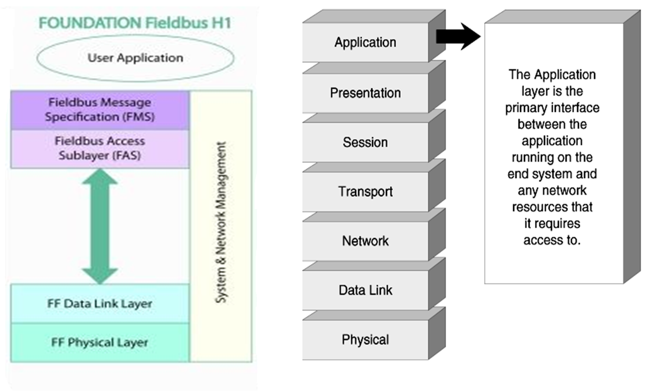 |
| OSI Layers |
- Fieldbus access sublayer- It is a virtual communication channel between two applications. It gives two types of channel
1. 1-to-1 bidirectional
2. 1-to-many unidirectional
- Fieldbus message specification- FMS provides different types of services foroperation and supervision of control system. For example, If user layer simply gives the value of temperature, FMS simply converts all the values in specific format.
- User layer- It is used to communicate with real world devices. It only provides some data or text or its context and request for communication.
- LAS (Link Active Scheduler) operation- It means it schedules the work for every activity on fieldbus network. It comprise of
1. CD Schedule
2. Link List Maintenance
3. Data Link Time Synchronization
4. Token Passing
2. Devices can be powered directly from the fieldbus and operate on wiring that was previously used for 4-20mA devices.
3. The H1 fieldbus supports intrinsically safe fieldbus with us powered devices.
4. The length of the fieldbus determined by the communication rate, cable type, wire, size, bus power option and I.S. option.
1. Its speed is around 100 MBPS with length up to 100M
2. Generally it connects input/output subsystems, host systems, linking devices and gateways.
During setting of Foundation fieldbus networks in field, engineers required a datasheets of devices, segment protector, host etc. Means they require total information about any device which is going to connect to a which segment or which host. For that purpose they made a design of Foundation fieldbus segments in Designmate software and give it to field engineers for reference. For example as shown in picture below.
Foundation Fieldbus Types
- H1 fieldbus
2. Devices can be powered directly from the fieldbus and operate on wiring that was previously used for 4-20mA devices.
3. The H1 fieldbus supports intrinsically safe fieldbus with us powered devices.
4. The length of the fieldbus determined by the communication rate, cable type, wire, size, bus power option and I.S. option.
- HSE (High Speed Ethernet)
1. Its speed is around 100 MBPS with length up to 100M
2. Generally it connects input/output subsystems, host systems, linking devices and gateways.
Industrial procedure to set a Foundation Fieldbus communication
 |
| Fieldbus segment wiring |
Practical Demonstration-
Components of Complete fieldbus foundation segments-
1. Host or controller (May be dual or redundant)
2. FFPS (Foundation fieldbus power supply)
3. Segment protector
4. Your field devices
It is comprise of a first component as a Host or main controller, second component is foundation fieldbus power supply then we have trunk cable which connected to a segment protector used for field distribution and then your individual field connections to foundation fieldbus devices.
Host
The first component in any foundation fieldbus segment is H1 interface module, here we have connected a H1 connection to Delta V DCS as shown in figure below,
 |
| DeltaV host with Fieldbus H1 card |
This connection could be with any DCS like yokogawa, Honeywell, ABB etc. It is independent of manufacture. But the host is where your all controlling will be done and this is what a LAS means link active scheduler. It means it schedules the work for every activity on fieldbus network.
FFPS
The second component is power supply following picture will shows the example of pepperl Fuchs foundation fieldbus power hub.
 |
| pepperl Fuchs foundation fieldbus power supply |
Segment protector
The third component for foundation fieldbus segment is for field devices distribution. Following picture shows the pepperl Fuchs Segment protector. The segment protectors offers a short circuit protection. You can additionally connect more segment protectors in daisy chain topology by removing terminator cap and connect another segment.
 |
| Field distributer |
Field Devices
It is the fourth component of fieldbus segment. It should be noted that device must be compatible for foundation fieldbus regardless of any manufacturer or vendor. It means fieldbus devices support interoperability. The picture shown below shows FF compatible field device.
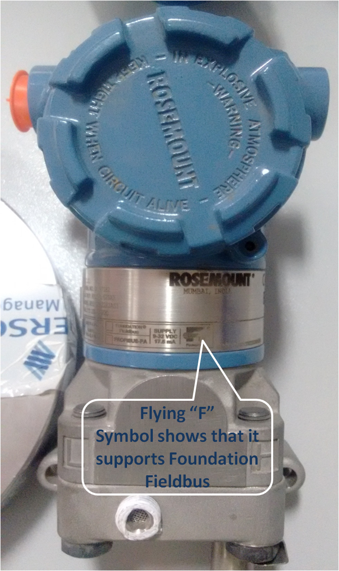 |
| FF compatible Temperature transmitter |
For more information click here
For wiring demonstration click below...
9 comments
Write commentsgood information on ff
Replynice &short information...
ReplyGood Information
ReplyThanks...Some of above information is related to industrial handling of FF communication
ReplyThis is very good sir... very important information for students... :-bd
Replythis is very good article on FF, sir...!! :-bd
ReplyIt is nice to have you as a teacher in our institute sir...
Replygreat to see this one: https://digiosense.com/
ReplySir, it's very nice information.
ReplyEmoticonEmoticon